Using OWON PC virtual oscilloscope to test automobile magnetoelectric crankshaft position sensor
With the increasing popularity of cars, the use of automotive electronic sensors is more and more. How does an oscilloscope measure these sensors on the car? Let's use OWON virtual oscilloscope to see how to use it.
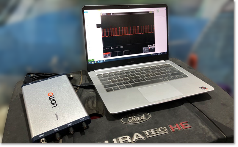
Prepare a notebook computer and an OWON VDS2064 digital oscilloscope, open the computer, install the PC software, connect the wire, and start to test the magnetoelectric crankshaft position sensor.
The magnetoelectric crankshaft position sensor can generate its own signal without additional power supply. When the metal wheel rotates, the magnetic field changes, and the voltage generated in the circuit changes.
When the magnetoelectric crankshaft sensor works, the amplitude is not exactly the same. When the speed increases, the amplitude increases. At the same time, it also reflects the difference between the four stages of engine operation, namely, intake, compression, work, and exhaust. Therefore, measuring the waveform of a crankshaft sensor with an oscilloscope can completely reflect whether the mechanical operation is normal. Here is an example.
This is the waveform of a Weichai WP7 Zoomlion crane engine three months after overhaul. The engine can not be accelerated to 1900 rpm. As long as the engine pressure relief valve is opened at 1900 rpm, the engine turns to 1500 rpm. No further maintenance was carried out at that time.
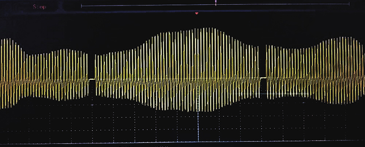
(5ms/div, 10V/div)
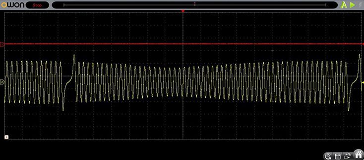
Four months later, the highest speed of the engine is only 1500 rpm. The waveform measured by OWON VDS2064 virtual oscilloscope is as follows. We find that the amplitude difference of waveform is further enlarged.

(10ms/div, 10V/div)
Check the signal panel to see if there is any abnormality. It is determined that the engine crankshaft moves forward and backward or up and down. Pry the front belt pulley of the crankshaft with a flat crowbar, and the movement clearance is very small, so it is found that the crankshaft has been "holding the Bush". As a result, the upper and lower runout of the crankshaft is too large.


Sometimes it is not necessary to detect the primary and secondary waveforms of ignition to indirectly judge the misfire of a certain cylinder. Assuming that a certain cylinder does not work, it may not do work when the cylinder is supposed to do work, resulting in the decrease of crankshaft speed. This can be reflected in the waveform of the crankshaft position sensor.
In the circuit diagram, the two terminals of the magnetoelectric crankshaft position sensor are different. For ECU, these two terminals cannot be connected in reverse.
If the connection is reversed, the normal connection is different from the abnormal connection by "half a tooth". This may cause the timing error, or the ECU thinks that the timing is wrong.

The figure below is the Great Wall pickup Fengjun 6 country 5 model. The crankshaft sensor uses an oscilloscope to measure the normal waveform and the waveform after the terminal is reversely connected.
(5ms/div, 10V/div)
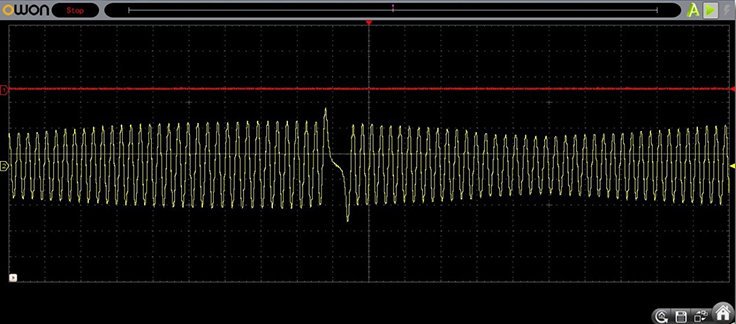 (5ms/div, 10V/div)
Using OWON VDS2064 PC virtual oscilloscope to measure the waveform, the details of the waveform can be clearly seen through the computer screen, which is convenient for analysis. It is a good helper for the automobile maintenance personnel.
OWON VDS Series PC Oscilloscope
Automobile maintenance engineers are very fond of PC virtual oscilloscope in their working process. Its ultra-small body makes it easier to carry and use. However, most of the PC virtual oscilloscopes on the market have been more or less deleted compared with the desktop oscilloscopes, which makes it difficult for engineers to carry out normal measurement work. When portability and performance conflict, how to choose? You can take a look at OWON Lilliput's VDS PC oscilloscope.

- Up to 100MHz bandwidth, and max 1GS/s real-time sample rate
- 10M record length
- Friendly UI: FFT, or X-Y, and waveform 2 views displayed
on the same screen
- Multi-trigger option: edge, video, slope, pulse, and alternate
- USB isolation - less signal inference, more PC protection
- USB bus powering, and LAN remote control (optional)
- Ultra-thin body design, easy portability

Related News
- Invitation | Owon invites you to the electronica exhibition. Visit us at A3 667!
- OWON Hong Kong Autumn Electronics Fair Concluded Successfully!Here's A Brief R..
- OWON Invites You To The Hong Kong Electronics Fair Autumn Edition 2024
- OWON Launches New OWH67 High-Power Programmable DC Power Supply
- Master With Precision|OWON Launches HDS120 Multi Functional Oscilloscope Multi..
- Silent Operation, Silent Power | OWON SPS Series Single-Channel Programmable D..
- Successful ending | The excitement never ends and we look forward to seeing yo..
- Inviting You To The Automotive Test Expo--Your Arrival Is Anticipated
- OWON Sincerely Invites You To Participate in The Middle East Educational Techn..
- OWON Sincerely Invite You To Hong Kong Autumn Electronics Fair